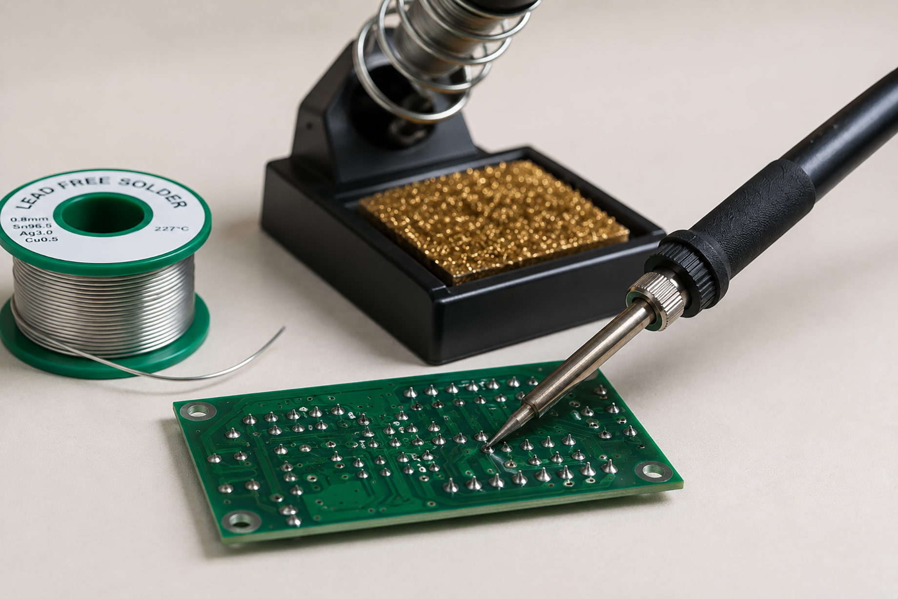
Solder joint defects can create immediate failure or an intermittent problem that appears later. Many are caused by poor heat transfer, contaminated surfaces, wrong tip choice, excessive movement, or uncontrolled rework.
Understanding the defect and its cause is better than simply adding more solder.
Use Suitable Equipment
A temperature-controlled station provides more consistent heat than an uncontrolled iron.
Technicians can compare electronic soldering tools including stations, tips, hot air, desoldering tools, and accessories.
Choose a tip that makes broad contact with the joint. A tiny pointed tip often transfers heat poorly to large pads.
Cold or Disturbed Joints
A dull, irregular joint may form when parts move before solder solidifies or when surfaces do not reach the correct temperature.
Secure the board and component. Heat both pad and lead, apply solder to the joint, and allow it to cool without movement.
Do not rely on appearance alone; alloy and flux affect finish.
Insufficient Wetting
Solder may form a ball without spreading across the pad or lead. Causes include oxidation, contamination, weak flux, or inadequate heat.
Clean surfaces using the approved process. Use fresh solder and suitable flux.
If a component lead is badly oxidized, replacement may be safer than prolonged heating.
Excess Solder
Too much solder can hide the joint shape, create bridges, and make inspection difficult.
Remove excess with wick or a desoldering tool. Then reflow using enough solder to create a controlled fillet.
Do not leave large blobs as mechanical reinforcement. The joint and component support should be designed correctly.
Solder Bridges
Bridges connect adjacent conductors unintentionally. They are common on fine-pitch parts when solder, tip size, alignment, or flux is poorly controlled.
Use magnification and good lighting. Remove excess with clean wick and inspect again.
Check hidden pins with appropriate electrical testing.
Lifted Pads
Pads can separate from the board after excessive heat, long dwell time, repeated rework, or mechanical force.
Use an efficient tip at a controlled temperature. Preheat large boards where the process permits.
Do not pull a component until solder is fully molten. A lifted pad may require an approved repair or board replacement.
Damaged Through-Holes
Forcing pins from a partly molten joint can damage barrel plating.
Use a powered desoldering tool or wick appropriate to the job. Clear each hole before removing the component.
Support the board and avoid twisting the part.
Flux Residue
Some residues are designed to remain, while others require cleaning. Wrong cleaning can spread contamination or damage plastics.
Follow the flux and assembly process. Use approved solvent, brush, and drying.
Inspect under components where residue or moisture may remain.
Tip Oxidation
An oxidized tip does not wet with solder and transfers heat poorly. Users may respond by increasing temperature, which worsens damage.
Keep the tip tinned, use approved cleaning, and reduce temperature during idle periods. Replace tips when plating fails.
Sleep functions can extend tip life.
Wrong Alloy or Temperature
Different solder alloys have different melting and wetting behavior. Use the alloy specified for the product and avoid mixing unknown wire at the bench.
Set temperature for the process, tip, and joint. A higher display number does not guarantee faster work when the tip is oxidized or too small.
Allow the station to recover between demanding joints instead of holding the iron on the board for a long time.
Thermal Damage
Discolored boards, melted connectors, and damaged components indicate excessive heat or poor protection.
Use heat shields, suitable nozzles, controlled airflow, and minimum effective dwell time.
For rework, established soldering station manufacturers can be compared for temperature control, tip systems, replacement parts, and support.
ESD Damage
Electrostatic discharge may not leave a visible solder defect but can damage the device during repair.
Use grounded mats, wrist straps, ESD-safe tools, and suitable storage. Verify the control system regularly.
Inspect Systematically
Use magnification to check wetting, bridges, cracks, pad damage, and alignment.
Compare with an approved workmanship standard for the product. Perform electrical and functional testing after visual inspection.
Document unusual damage before and after repair.
Use a Controlled Repair Technique
Stabilize the board and component. Apply flux only where needed, heat both surfaces, feed a controlled amount of solder, and remove the iron without moving the joint.
For hot-air work, shield nearby parts and use the lowest practical airflow. Confirm component orientation before heating.
Let the board cool naturally unless the approved process specifies another method.
Standardize Rework
Create instructions for common repairs, including tools, temperature range, tip, flux, cleaning, and inspection.
Track repeat defects. If the same joint fails again, investigate design, component, vibration, or production issues.
Train with Representative Samples
Practice on scrap or training boards before repairing valuable assemblies. Include fine-pitch parts, connectors, ground planes, and through-hole removal.
Assess tip choice, dwell time, pad protection, cleaning, and inspection—not only whether the circuit works once.
Refresh training when tools, solder alloy, or workmanship standards change.
Record Defects and Verify the Result
Log the defect type, board location, suspected cause, repair method, and inspector. Repeated defects in the same area may point to poor thermal design, contamination, or an assembly-process problem rather than individual technique. After repair, perform the required electrical test as well as visual inspection. A joint that looks acceptable is not proof that the circuit works reliably.
Conclusion
Good solder joints come from clean surfaces, correct heat transfer, stable parts, suitable flux, and controlled inspection.
Do not fix every defect by increasing heat or adding solder. Identify the cause, use the right tool, and verify the repaired assembly. This reduces repeat failures and protects the board from unnecessary damage.