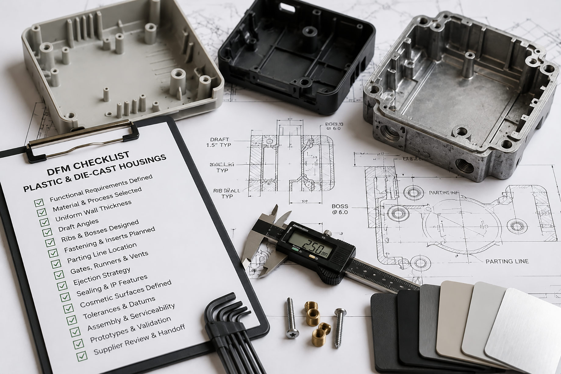
Product housings protect components, provide mounting points, and shape the user’s experience. Plastic injection molding and metal die casting can both produce complex housings, but each has different design rules.
Design for manufacturing should begin before tooling.
Define Functional Requirements
Record:
- Internal components
- Mechanical load
- Temperature
- Impact
- Ingress protection
- Electrical insulation
- EMI shielding
- Heat dissipation
- Weight
- Appearance
- Annual volume
These requirements help select material and process.
Choose Plastic or Metal
Plastic supports low weight, electrical insulation, color, and integrated clips. Metal offers stiffness, conductivity, shielding, and heat performance.
Do not choose only from appearance. Compare the complete assembly, including inserts, coatings, and fasteners.
Keep Walls Consistent
Uniform walls promote balanced filling and cooling.
Injection-molded plastic can sink or warp around thick sections. Die-cast metal can develop porosity and thermal hot spots.
Core out heavy areas and use ribs where appropriate.
Add Draft
Draft helps the part leave the tool without scraping or distortion.
Required draft depends on depth, texture, material, and process.
Discuss draft early with the toolmaker instead of adding it after the design is frozen.
Design Ribs and Bosses
Ribs add stiffness without thick solid walls. Bosses support screws and components.
For plastic injection mold manufacturing, rib and boss thickness should reduce sink while maintaining strength.
Use fillets and support tall bosses. Avoid placing heavy features behind cosmetic surfaces.
Plan Fastening
Options include molded threads, self-tapping screws, inserts, machined threads, clips, and separate brackets.
Consider assembly cycles, repair, vibration, and torque.
Metal housings may need machining at critical threaded features. Plastic inserts require suitable installation and pullout design.
Locate Parting Lines
The parting line affects appearance, flash, sealing, and trimming.
Place it away from critical gasket surfaces and visible areas where possible.
Undercuts may require slides or lifters, adding cost and maintenance.
Plan Gates and Overflows
Injection-mold gates influence flow, weld lines, packing, and visible marks.
Die casting needs gates, runners, vents, and overflows for high-speed metal flow.
Keep these areas away from critical features when possible and allow removal.
Design Cooling and Thermal Balance
Uneven cooling increases cycle time and distortion.
Tool designers need space for channels around critical areas. Thick bosses and corners can be difficult to cool.
For metal parts, die temperature and local cooling influence porosity and tool life.
Address Ejection
Provide areas for ejector pins or sleeves without damaging visible or sealing surfaces.
The part must remain on the intended tool side during opening.
Deep texture, low draft, and large flat surfaces increase ejection force.
Plan Sealing
For an IP-rated enclosure, define gasket path, compression, fastener spacing, surface flatness, and cable entries.
Avoid parting lines, ejector marks, or porosity in critical sealing areas.
Test the assembled housing, not only individual parts.
Consider Die-Cast Alloy
Aluminum die casting components offer low weight and useful mechanical and thermal properties. Zinc can fill fine features, while magnesium provides very low density.
Compare corrosion, finish, strength, casting behavior, and supply.
Define Cosmetic Surfaces
Mark visible areas and acceptable defects on the drawing.
Texture can hide minor variation but affects draft. Metal finishes may include coating, plating, polishing, or machining.
Approve physical samples under defined lighting.
Set Tolerances Carefully
Identify critical datums and assembly dimensions. Avoid tight tolerances everywhere.
Plastic shrinkage and metal-casting variation need process-appropriate limits.
Plan secondary machining only where needed.
Review Assembly
Check tool access, fastener count, cable routing, component insertion, and mistake-proofing.
Reduce parts where integration does not make tooling too complex.
Use prototypes to confirm fit, but validate production-intent samples for material and process performance.
Use Simulation Selectively
Flow, cooling, warpage, and thermal simulation can expose risks before tooling is cut. Use the analysis to compare design options, not as a substitute for engineering judgment. The result depends on realistic material data, process assumptions, gate locations, and boundary conditions.
Focus detailed simulation on high-risk areas such as long flow paths, thick transitions, sealing faces, heat-producing components, and dimensionally critical bosses. Record the assumptions so the tooling and molding teams can challenge them during review.
Learn from Prototypes Without Overtrusting Them
Machined, printed, or soft-tool prototypes are valuable for checking assembly, ergonomics, connector access, and general packaging. However, they may not reproduce molded shrinkage, die-cast porosity, draft, ejector marks, or production surface finish.
State what each prototype is intended to prove. Use production-intent material and tooling trials for tests involving strength, sealing, heat, long-term creep, or appearance. This prevents a successful prototype from creating false confidence about mass production.
Build a Clear Supplier Handoff
The final data package should include controlled drawings, 3D files, material grades, cosmetic zones, critical dimensions, test methods, assembly requirements, and approved reference samples. Identify which dimensions are measured at the component stage and which are verified after assembly.
Hold a joint DFM review with molding, die-casting, finishing, and assembly suppliers. Close each action with an owner and date. After the first production run, compare actual defects and cycle data with the design assumptions. A disciplined handoff protects the intent of the design as it moves into tooling and production.
Finally, define a controlled approval process for any supplier-requested change. A small adjustment to a gate, alloy, resin, coating, or machining step can affect fit and performance elsewhere. Require documented review and suitable validation before the change enters normal production.
Conclusion
Good housing DFM balances function, material, wall thickness, draft, tooling, sealing, appearance, and assembly.
Involve injection molding or die-casting specialists before design release. Early changes are much less expensive than modifying a finished production tool.