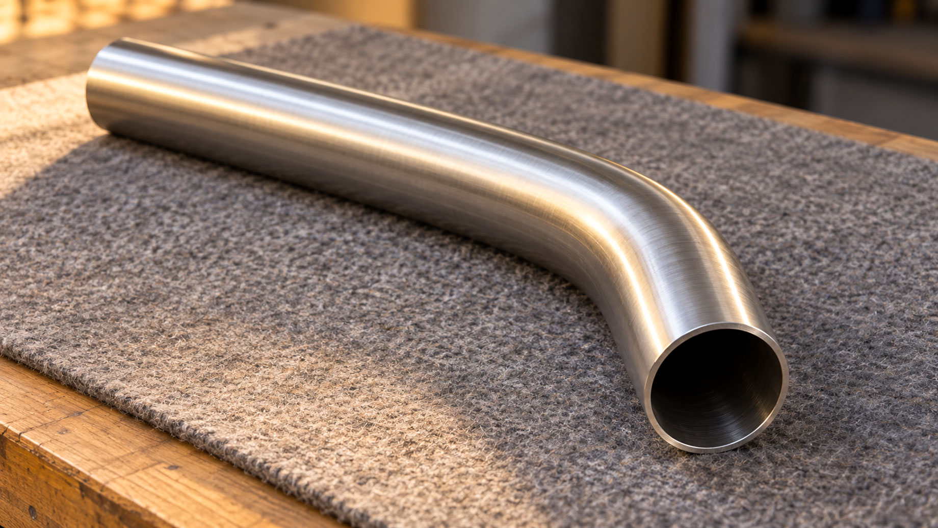
A curved metal frame can look effortless in a rendering and become difficult to specify once someone has to make it. For designers buying custom tubular furniture or interior components, bend radius and surface integrity need to be resolved together. CNC tube bending, mandrel support, a wiper die and springback compensation are manufacturing details with visible consequences for the finished object.
The productive conversation starts before the design is treated as fixed. Ask the fabricator which curves, connections and exposed surfaces need a physical sample, then give those features enough attention that the eventual approval represents the intended piece rather than an attractive fragment of it. A small change to the specification may be easier to assess at this stage than after the finished components arrive.
Turn the visual idea into a readable tube specification
Name the tube material and condition, outside diameter, wall thickness and desired centerline radius. Show the bend locations and final orientation. Those details give the equipment supplier and fabricator something concrete to review; a mood image cannot tell them which geometric compromises the designer would accept.
Zhuoran Machinery’s CNC bending guidance identifies material, tube dimensions, centerline radius and inspection requirements as inputs to machine selection. It includes furniture among potential applications, while keeping suitability tied to the particular geometry, tooling and production requirements.
Separate design intent from negotiable detail. If the appearance depends on a continuous curve beside a straight rail, show that relationship and explain which side will be visible. If the component must meet another part, identify the connection reference rather than expecting the supplier to infer it from the rendering.
Leave unanswered questions open. A drawing marked for feasibility review is more useful than a drawing carrying an assumed bend radius that nobody has checked against the selected tube and proposed process.
Treat a tighter curve as a forming decision
The Fabricator describes stretching and wall thinning around the outside of a bend, compression toward the inside and changes in the tube’s cross-sectional shape. Its technical account also explains springback after release and the relationship between the chosen forming method and the application.
Those effects matter when the curve is part of the visual design. A tube that follows the intended centreline can still look different if its section becomes visibly flattened or the inner bend develops wrinkles. Ask the fabricator which inspection criteria should accompany the radius requirement and how the proposed sample will make those conditions visible.
Compare the alternatives before choosing. Where the supplier proposes a different radius, ask for the reason and evaluate the effect on the overall piece, including its connections and spacing, rather than accepting or rejecting the change solely because it differs from the earliest sketch.
A mandrel or wiper die may be part of the proposed process, but neither term should be treated as a guarantee of a flawless decorative surface. Their application needs review against the actual tube, tooling and acceptance requirements.
Discuss hidden tooling behind exposed surfaces
Identify the surfaces people will see or touch. Show them on the drawing and ask how the proposed forming and handling route will be assessed against the intended appearance. This gives the fabricator a better question than a broad request for a premium finish.
The CNC guidance from Zhuoran Machinery includes mandrel support for thin-wall tubes and tight radii, a wiper die for wrinkle-sensitive applications and pressure-die support for controlled deformation. Tooling selection is connected to tube dimensions and the forming task.
Ask the fabricator to explain how that proposed support relates to the sample, including which surface conditions will be inspected and which aspects remain dependent on later finishing. A bending trial should not be described as proof of the final appearance when the intended finishing operation has not yet been represented.
Keep responsibility for cosmetic acceptance explicit. The designer may judge whether a visible surface meets the intended look, while the fabricator and engineering team check the specified geometry and other requirements. Record both decisions instead of allowing an attractive photograph to substitute for the entire review.
Use the released sample to judge the actual shape
Review the part after forming and release, using the agreed inspection references. Springback compensation belongs in the manufacturing discussion because the required finished geometry and the movement used to create it are not necessarily identical. The designer needs an accepted shape; the supplier needs evidence supporting the settings used to make it.
Zhuoran Machinery connects springback compensation with material, radius, tooling and actual sample results. Its sample validation guidance also includes the bend sequence, final orientation and inspection method rather than treating tube diameter as the complete requirement.
Check the sample in its intended relationship with adjacent components wherever the project permits it. A curved frame that appears balanced on a bench can reveal a different issue when aligned with the rails, panels or connection points that establish its position in the finished piece.
Retain the sample identity. Record the drawing revision, tube specification and agreed finish condition so that later reviewers can tell whether a new component belongs to the same approval, rather than comparing it with a reference piece whose material or processing history has been forgotten.
If the design changes, revisit the affected checks. A previous approval should not silently carry over to a revised radius or tube section merely because the furniture still has the same name.
Create an appearance review that purchasing can use
Agree an approval checklist before ordering the production batch. It should distinguish measurable drawing requirements from the visual comparison the designer expects to make, while giving the supplier a clear record of the sample condition that was accepted.
- Identify the drawing revision and the specified tube material and dimensions.
- Check the bend radius, final orientation and connection locations against the drawing.
- Inspect exposed bends for the agreed limits on wrinkles, flattening and surface marks.
- Record whether the sample represents the intended finish or an earlier manufacturing stage.
- Confirm the mandrel and wiper die arrangement where those tools form part of the approved route.
- Ask how springback compensation was established for the accepted material and geometry.
- Keep the approved sample reference available to purchasing and the production team.
For visual comparison, agree how the sample will be viewed and which surfaces matter most. An inspection approach that changes from a distant image to close examination under different lighting can produce disagreement even when neither party has changed the component.
Resolve the review record while the sample is available. A later message saying the finish should be better leaves the manufacturer guessing which observation should drive the next trial.
Know which design promises the sample cannot settle
A pleasing bend is evidence about that bend. It does not establish every load, stability, connection or installation requirement of a completed item, and the project team should retain the design checks and tests appropriate to the intended furniture or interior component.
Equipment suitability is also specific. A supplier’s statement that CNC tube bending can serve furniture applications does not establish approval for every proposed structure, nor does a sample review establish a certification that has never been supplied. Keep those claims out of the purchasing description unless the project has the relevant evidence.
During a discussion with Zhuoran Machinery, present the intended component and ask which manufacturing conditions need confirmation. The answer should connect the tube, radius, tooling and sample acceptance rather than replace the designer’s responsibility for the complete item.
Good design procurement leaves fewer assumptions between a drawing and the delivered piece. The curve has a defined geometry, its visible surface has an agreed reference, and the accepted sample has a traceable manufacturing context. That gives the design team a sound basis for judging the result without asking a rendering to carry decisions that only a real component can reveal.