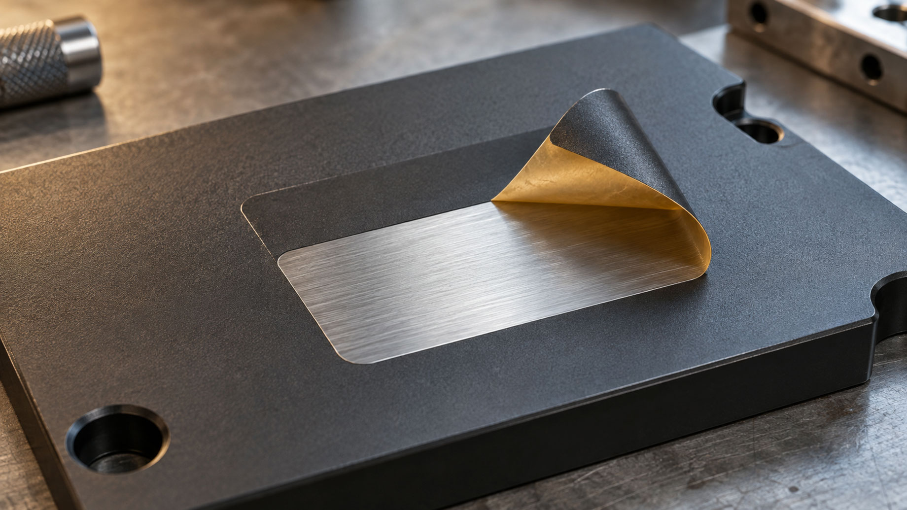
Coated metal components often include flat areas that must remain free of coating. Nameplate locations, gasket seats, bonding surfaces, logos, identification panels and machined faces may each require a defined, protected outline. For architects, specifiers, fabricators and production engineers, that boundary can be as relevant as the finish surrounding it.
Cutting standard masking tape by hand can make these outlines inconsistent and slow the masking operation. Custom masking shapes address this problem by defining the protected area before application. The choice between a die cutting machine and a cutting plotter then depends mainly on production volume and how frequently the geometry changes.
Why Flat Areas Need Defined Masking
Global Mask (Global Mask International SL) is an ISO-certified manufacturer of industrial masking products based in Spain. Its custom masking tapes for flat surfaces are made to measure for each part and process, using high-precision industrial die-cutting machines and cutting plotters.
The masking requirement starts with identifying which areas must remain uncoated. In a powder coating workflow, for example, a drawing may distinguish the surrounding coated face from a protected nameplate panel or gasket seat. These areas should be defined individually rather than left to interpretation during manual trimming.
For specification purposes, the useful distinction is between the overall component outline and the exact area requiring protection. A custom mask is designed around the latter, so its shape corresponds to the intended coating boundary.
How Custom Masking Shapes Are Developed
A custom piece of die-cut masking tape can be designed from a 3D drawing or the actual part. The shape is tailored to the component and its process, providing a repeatable outline for the flat area that needs protection.
This approach reduces the need to recreate the same shape manually for each component. Instead of repeatedly measuring and trimming standard tape, the masking operation uses a shape already defined for that application.
The supplier states that the benefits include reliable protection against paint, abrasives and chemical products; clean, sharp edges without paint bleed or residue; reduced manual masking time; and high repeatability across production runs. It also identifies cost optimisation and improved quality control as benefits.
Die Cutting Machine or Cutting Plotter?
A die cutting machine suits high-volume, repetitive production with fixed geometries. A cutting plotter suits short and medium runs, prototypes and designs that change frequently.
| Selection Factor | Die Cutting Machine | Cutting Plotter |
|---|---|---|
| Cutting Method | Custom-made steel die | Digital file, without a physical die |
| Production Fit | High-volume, repetitive runs | Short and medium runs; prototyping |
| Geometry | Fixed, repeatable shape | Custom or frequently changing designs |
| Main Advantage | Fast cutting and repeatability | High precision and immediate design changes |
| Cost Consideration | Low cost per part in large series | No die manufacturing cost |
With die cutting, the custom-made steel die establishes the fixed shape used throughout the run. This makes the method appropriate when the same masking geometry is required repeatedly and cutting speed and unit cost are priorities.
A plotter works directly from a digital file. Changes can therefore be made without manufacturing a physical die, making this route appropriate for product development or production involving changing outlines. Its flexibility also suits shorter runs where a dedicated die is less appropriate.
Neither method should be selected on volume alone. A frequently revised shape may favour a plotter, while a stable geometry repeated across a large series may favour die cutting.
Connecting the Specification to Production
A practical masking brief should identify the protected flat areas, the intended coating boundaries, the relevant part drawing or physical sample, the process and the expected production run. It should also establish whether the geometry is fixed or still subject to revision.
This gives the specifier, fabricator and production team a common reference for the masking shape. Quality checks can then consider whether the intended area remains free of coating, whether the edge is clean and whether residue is present after removal.
For coated metal components, the selection follows two linked requirements: a masking shape matched to the protected area, and a cutting method matched to the production pattern. Fixed geometries in large repetitive runs favour die cutting; shorter runs and changing designs favour a plotter.